


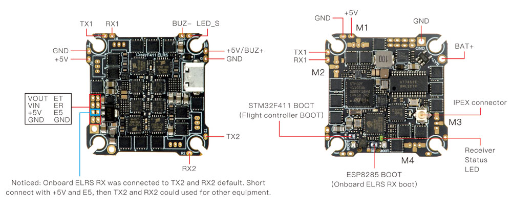
*”ET” and “ER” pads are used for communication with ESP8285, you can connect “TX” of FTDI tool to “ET” pad and connect “RX” of FTDI tool to “ER” pad for upgrade onboard UART ELRS receiver firmware. Need to short connect “+5V” and “E5” pads before that.
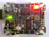
The CrazyF411 ELRS flight controller comes with integrated UART 2.4GHz ExpressLRS receiver and 20A Blheli_s ESC(Bluejay firmware pre-installed) which could support 2-4s. Bigger Mosfet could support high to 20A currents would be better for 2-4S toothpick drone or long range FPV drone. And because the 2.4GHz ExpressLRS receiver is equipped with the SX1280 radio frequency chip with high sensitivity, high packet rate and low latency, this flight controller is the one that all Race/Freestyle pilots needed. The built-in ELRS receiver is UART communication with MCU, it’s the same like Happymodel EP1 which you can update firmware by betaflight pass-through or WIFI, very simple. The default firmware is ELRS V3.0.1. This flight controller would be used for Crux35 to instead ELRS X1 flight controller.
***Thanks to our team pilot “Jiggy” provide the bind instruction Alternative-Binding-Method-for-UART-Based-ELRS-RX
Specifications:
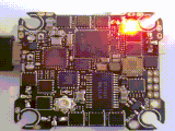
| Flight controller | MCU:STM32F411CEU6 (100MHZ, 512K FLASH) Sensor: ICM42688P or BMI270 (SPI Control) Mount pattern: 25.5×25.5 M2 Size:32*28*9mm Power supply: 2-4S Lipo battery Built-in 20A Blheli_s ESC each Built-in Betaflight OSD(SPI Control) Built-in UART ExpressLRS 2.4GHz receiver Built-in 5V 1.5A BEC Flight controller firmware target: CRAZYBEEF4DX |
| Onboard 4in1 ESC | MCU upgraded to EFM8BB21 Power supply: 2-4S LiPo/LiPo HV (7v/17v) Currents: 20A continuous peak 25A (5 seconds) Support BLHeliSuite programmable Factory firmware: Bluejay 0.18.1Firmware target: F_H_40_48_v0.18.1 Default protocol: DSHOT150/DSHOT300/DSHOT600 |
| Onboard UART ExpressLRS 2.4GHz Receiver | Packet Rate option: 25Hz/50Hz/150Hz/250Hz/500Hz RF Frequency: 2.4GHzAntenna plug: IPEX Telemetry output Power: <12dBm Receiver protocol: CRSF Default firmware version: ExpressLRS V3.0.1 Firmware target:HappyModel EP1/2 2400 RX |
| Onboard voltage and Amperage meters settings | Voltage meter scale setting 110 Amperage meter scale setting 470 |
Binding procedure:
- Supply power to the flight controller by plug USB, wait until the green LED on the FC is off, immediately turn off the power, and then repeat again the above steps. When the FC is powered on for the third time, the green LED light will start to double-flash, which means that the RX enters the binding mode
- Please make sure your ExpressLRS tx module firmware is v3.x.x. And go to ExpressLRS.lua from “TOOLS” menu of your radio transmitter. Then hit [Bind] to binding with the onboard ExpressLRS receiver. The green LED should blinking slowly first then turn to solid, that means binding was successfully. If the green led still keep double flash after binding ,please change Model Match tab value from “off” to “on” or from “on” to “off”
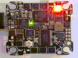
Receiver LED status meanings:
Green LED solid means bind successful or RC link established; Green LED double-flash means get into bind mode; Green LED flash slowly means no RC signal input from TX module; Green LED continuous flash fast means ExpressLRS wifi enabled.
 Bind successful
 Bind mode
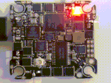 No RC Input
 Wifi mode